

 English
 русский
 Español
 عربى
عربىDon't hesitate to send a message

Extension Cord Wiring Diagram: Color Codes, Gauge, and Safe Connection
Content
- 1 What an Extension Cord Wiring Diagram Shows
- 2 Standard Wire Color Codes for Extension Cords
- 3 Extension Cord Internal Construction
- 4 How to Read a Wiring Diagram
- 5 Step-by-Step: Wiring a Male Plug
- 6 Step-by-Step: Wiring a Female Receptacle
- 7 Determining the Correct Wire Gauge
- 8 Twist-Lock and High-Amperage Configurations
- 9 Common Wiring Mistakes and Safety Hazards
- 10 How to Test an Extension Cord After Wiring
- 11 Wiring an Extension Cord for Outdoor Use
- 12 When Should You Replace Instead of Repair?
- 13 Matching Extension Cords to Equipment and Applications
- 14 Selecting a Quality Extension Cord from a Manufacturer
You open the box of your new workshop and find a heavy-duty extension cord with a cracked plug. The cord itself is still in good shape, but the plug is unusable. A replacement plug costs very little, and a wiring diagram is all you need. The truth is, extension cord wiring is one of the simplest electrical jobs you can do safely—if you understand the color code, the wire gauge, and the load requirements.
Before you pick up a wire stripper, you need to know what the internal wires actually do. Every cord has a line (hot) conductor, a neutral conductor, and a ground conductor. The wiring diagram shows how those conductors map to the prongs on the plug and the slots on the receptacle. Once you can read that diagram, you can replace any damaged end, build a custom extension cord, or troubleshoot a cord that is not working.
What an Extension Cord Wiring Diagram Shows
An extension cord wiring diagram is a visual guide that details the electrical connections between the male plug, the female receptacle, and the internal conductors. It is not just a drawing; it is a specification for how the cord must be built.
At its simplest, a diagram shows the following elements:
- Male plug prongs, labeled as hot, neutral, or ground.
- Internal wire colors that correspond to each conductor.
- Female receptacle terminals, where the load connects.
- Strain relief locations that keep the cord from pulling the wires loose.
You may also see a table or a gauge chart near the diagram. This table tells you the maximum current in amps that the cord can handle based on the wire size (AWG) and the length of the run. A long cord increases voltage drop, so a diagram for a 100-foot cord may require a different wire gauge than a diagram for a 10-foot cord.
For a manufacturer, the diagram is the quality control blueprint. Every model produced in a factory needs to match the diagram exactly, because a miswired cord can cause short circuits, fires, or shock. A good wiring diagram also shows which side of the plug connects to the line conductor and which side connects to the neutral conductor, so the polarity is preserved at every outlet.
Standard Wire Color Codes for Extension Cords
The most important part of any wiring diagram is the wire color code. In most regions, the colors are standardized so that you can identify the function of each conductor at a glance. If you understand these colors, you can read most any extension cord diagram.
United States and Canada (NEMA)
In North American cords that follow the National Electrical Code (NEC), the standard colors are:
- Black or red: Hot (live) conductor - carries current to the load.
- White: Neutral conductor - returns current to the source.
- Green or bare copper: Ground conductor - provides a path for fault current to trip a breaker.
European Union (IEC)
European cords using the IEC color scheme use:
- Brown: Live (phase) conductor.
- Blue: Neutral conductor.
- Green and yellow striped: Earth (ground) conductor.
United Kingdom (BS 1363)
UK cords typically share the same colors as the EU: brown for live, blue for neutral, and green/yellow for earth. Older cords may have red for live, black for neutral, and green for earth, but if you are working on a modern cord, the IEC colors are the reference.
| Region | Live / Hot | Neutral | Ground / Earth |
|---|---|---|---|
| North America | Black or Red | White | Green or Bare |
| European Union | Brown | Blue | Green/Yellow |
| United Kingdom | Brown | Blue | Green/Yellow |
When you read a wiring diagram, always look for a color legend. If the diagram shows the colors but the cord you are repairing has old colors, do not guess. A multimeter continuity test will tell you which wire goes to which prong, and that is the safest way to confirm the wiring before you connect it to power.
Extension Cord Internal Construction
An extension cord is more than three wires in a jacket. The construction determines its voltage rating, temperature rating, flexibility, and resistance to oil or moisture. A wiring diagram alone will not show the outer jacket type, but the diagram should be paired with a cord specification that includes the jacket material.
Common cord types include:
- SPT-1 and SPT-2: Parallel cords with two or three flattened conductors. Often used for light-duty indoor cords. The two conductors are molded side by side in a flat ribbon.
- SJT and SJTW: Round, heavy-duty cords with stranded conductors and a weather-resistant jacket. The W indicates it is approved for outdoor use.
- SOOW: Extra-heavy duty cord with an oil-resistant rubber jacket, suitable for industrial environments. The wires inside are stranded for flexibility.
The wiring diagram will only show the conductors, but the cord jacket type is equally important. For example, a 14 AWG SOOW cord with three conductors can carry 15 amps at 125 volts. A diagram for that cord will show three color-coded wires inside a yellow or orange jacket. On the other hand, a light-duty SPT-2 cord with 18 AWG may only carry 10 amps, even if the plug is rated at 15 A.
Every cord also needs a strain relief mechanism. When you pull the cord, the strain relief transfers the tension to the outer jacket rather than the wire terminals. Without a strain relief clamp, repeated stress will break the wires at the connector. A good wiring diagram will show the strain relief as a separate component that must be tightened fully after the terminals are connected.
The temperature rating also affects the safe current. A cord with a 60°C jacket may be rated lower than the same gauge in a 105°C jacket. If the cord will be used near a heater, a motor, or in direct sunlight, the jacket material and its temperature rating should be checked against the application.
How to Read a Wiring Diagram
Reading a wiring diagram is like reading a map. You start at the power source, travel through the wires, and arrive at the load. Let's walk through a typical diagram for a 3-prong extension cord.
The diagram will show the male plug at one end. The smaller prong is the hot blade, the larger prong is the neutral blade, and the round pin at the bottom is the ground pin. Inside the plug, the black wire connects to the hot blade, the white wire connects to the neutral blade, and the green wire connects to the ground pin.
Following the cord to the female end, the diagram shows the hot wire terminating at the narrow slot, the neutral wire terminating at the wide slot, and the ground wire terminating at the U-shaped opening. In a correctly wired cord, hot is hot, neutral is neutral, and ground is ground at both ends.
Diagrams also use symbols. A straight line represents a wire, a dot represents a junction, and a small open rectangle might represent a terminal. Some diagrams include arrowheads to indicate current flow, though extension cord diagrams rarely show current direction. You may also see the letters H and N for hot and neutral, and G for ground. In many European diagrams, the letters L and N are used instead.
When you encounter a diagram with more than three wires, such as a 4-prong 30A or 50A plug, the color code expands. For a 240V/30A NEMA 14-30 plug, the wiring is black, red, white, and green: two hot legs, one neutral, and one ground. The diagram will show the two hot legs terminating at the two angled prongs, the neutral at the straight prong, and the ground at the L-shaped pin. This is common for dryers, ovens, and large portable generators.
Another common diagram is for a 240V/50A NEMA 14-50 plug. This plug has four prongs: two hot, one neutral, and one ground. The diagram will show the two hot wires connected to the two outer prongs, the neutral to the side prong, and the ground to the bottom prong. The physical arrangement of the blades is crucial here, because a miswired 50A cord can energize the wrong parts of the receptacle and destroy a costly appliance.
If you are reading a diagram for a 2-prong cord, there is simply no ground conductor. The diagram will show only hot and neutral, and the plug will have two blades of unequal width. A 2-prong cord cannot be safely grounded, so it should only be used with tools that are double-insulated and do not require a ground connection.
Step-by-Step: Wiring a Male Plug
Now let's apply the diagram to a real repair. You are replacing a damaged male plug on a SJTW 14 AWG cord. Follow these steps carefully.
Tools You Will Need
- Wire strippers with slots for 14 AWG and 16 AWG.
- Diagonal cutters.
- Small screwdriver.
- New replacement male plug with terminals.
- Heat shrink tubing or electrical tape (optional).
- Multimeter for testing.
Step 1: Unplug and Inspect
Make sure the cord is completely disconnected from any power source. Cut off the damaged plug with diagonal cutters. Leave at least an inch of the outer jacket intact. If you see any melted insulation or blackened wires inside, inspect the cord for damage further back. If the damage extends deep into the jacket, replace the entire cord.
Step 2: Strip the Outer Jacket
Use a knife or wire stripper to remove about 1.5 to 2 inches of the outer black or orange jacket. Be careful not to nick the inner conductors. If the cord is round SJ type, you can use a utility knife to make a shallow lengthwise cut and peel the jacket back. Cut radially around the jacket and slide the jacket off the inner wires.
Step 3: Strip the Individual Wires
Inside you will find black, white, and green wires. Strip about 1/2 inch of insulation from the end of each conductor. Twist the strands of each wire tightly so they are ready for the terminal. Use the wire strippers to avoid nicking the copper strands. A clean, even twist prevents stray strands from touching adjacent terminals.
Step 4: Connect to the Plug Terminals
Most replacement plugs use screw terminals or a clamping mechanism. Refer to your wiring diagram: black goes to the brass-colored screw (hot), white goes to the silver-colored screw (neutral), and green goes to the green screw (ground). Wrap the wire around the screw in the direction of tightening, or insert it into the terminal clamp and tighten it down. Make sure the wire is firmly clamped and no bare copper is visible outside the terminal.
Step 5: Secure the Strain Relief
Your new plug has a strain relief clamp or a boot that fits over the outer jacket. Slide the clamp in place and tighten the screws so the outer jacket is held firmly. Do not clamp so hard that you crush the cord. The strain relief should prevent the inner wires from being pulled when the cord is tugged.
Step 6: Reassemble and Test
Reattach the plug housing and secure the screws. Use a multimeter to check continuity between each prong and the corresponding wire end at the other side. Touch the probes to the prongs and the other ends of the stripped wire. The meter should beep for hot, neutral, and ground. Also test that the hot and neutral are not shorted together. Always test before plugging in.
If you are not comfortable with this work, hire a qualified electrician. But if you follow the diagram carefully, replacing a plug is a straightforward job that most tool owners can tackle in under thirty minutes.
Step-by-Step: Wiring a Female Receptacle
The female end is the one that accepts a plug. Over time, the contacts can loosen or the cord can break internally. The wiring process is similar to the male plug, but the internal layout differs.
Cut off the damaged receptacle and strip the outer jacket. Inside the female connector body, you will find terminals labeled or color-coded. The black wire goes to the brass terminal, white to silver, green to ground. In most standard household connectors, the receptacle has a single set of terminals, so each conductor connects to exactly one screw.
One common issue is that the receptacle may have two brass terminals and two silver terminals if it has multiple slots. In a standard 15A/125V receptacle, the wiring diagram shows each conductor connected to only one terminal. When the cord has 3 conductors, it is a single-circuit connector, and the unused terminals are simply not connected. Some multi-outlet connectors use a daisy-chain arrangement where the hot wire is split to both brass terminals, but this is only necessary when the connector has two separate outlets.
Secure the wires, install the strain relief, and reassemble the housing. Test the female end for continuity with a multimeter by inserting a test probe into the narrow slot (hot) and the other probe into the wide slot (neutral). Then test the ground slot to the U-shaped opening. If the cord is a multi-outlet type, repeat the test for each outlet position.
When replacing a female receptacle, always use a connector that matches the plug type and the current rating. A 20A receptacle should not be used with a 15A plug? Actually, a 20A receptacle is sometimes used with 15A cords, but the reverse is not safe. Follow the wiring diagram supplied with the connector, and if the receptacle has a “20A” rating plus a T-shaped neutral slot, you need to confirm that the cord wire gauge and plug rating are compatible.
Determining the Correct Wire Gauge
One of the most common mistakes people make with extension cords is using a gauge that is too small for the load or too small for the length. A wiring diagram alone does not tell you the gauge; you need a wire gauge chart and a look at the manufacturer's rating.
The American Wire Gauge (AWG) system is used in North America. The smaller the gauge number, the larger the wire. A 16 AWG wire is thinner than a 12 AWG wire and carries less current. The ampacity of a wire also depends on the insulation type and the temperature rating.
| Wire Gauge (AWG) | Maximum Ampacity at 60°C | Typical Use |
|---|---|---|
| 16 AWG | 13 amps | Lamps, small household appliances, indoor devices |
| 14 AWG | 15 amps | Power tools, heaters, standard household equipment |
| 12 AWG | 20 amps | Heavy-duty tools, large power equipment |
| 10 AWG | 30 amps | RVs, generator connections, heavy machines |
Length matters. The voltage drop over a long run can reduce the voltage delivered to your tool. A 16 AWG cord that is 50 ft long may not start a 15 amp saw. The wiring diagram often includes recommended maximum lengths for each gauge. If you need to power a high-current appliance, choose a lower gauge number (thicker wire).
You can approximate voltage drop with a simple rule: for a 120V circuit, a loss of 3% or less is generally acceptable. If you are running a 15A load, a 14 AWG cord can go about 50 feet before exceeding a 3% drop. A 12 AWG cord can go about 100 feet. Using a thicker wire than necessary adds cost and weight, but it is always safer.
If you are building a custom extension cord, you must match the wire gauge to the plug rating. A plug rated at 15 A should never be used with a cable having a lower ampacity unless the load never exceeds the lower limit. For example, a cord with 16 AWG cable and a 15 A plug is a common mismatch in consumer products, but it is legal only if the appliance is fused or the current is limited. For a safe design, the cable ampacity must be equal to or greater than the plug rating.
Twist-Lock and High-Amperage Configurations
Some extension cords use twist-lock connectors, commonly seen in industrial or RV applications. The wiring diagram for these connectors is more complex because the connector has multiple blades arranged in a circle.
For example, a NEMA L14-30 twist-lock plug has four prongs: two hot, one neutral, and one ground. The blades are angled so they lock into the receptacle when twisted. The wiring colors for this configuration are black (hot), red (hot), white (neutral), and green (ground). The diagram will show the specific blade positions, because the twist-lock mechanism requires the blades to fit in a particular orientation.
For a 50 A RV cord, the plug may have four or five pins. A common 50 A generator cord uses a NEMA 14-50 plug. The wiring diagram shows two hot wires, one neutral, and one ground. When you read the diagram, you need to know which prong is which, because miswiring a high-amperage cord will damage equipment and create a fire hazard.
Some European and Australian cords also have special locking connectors. The Schuko plug in Europe has two live pins and a grounding clip, while the UK BS 1363 plug has a fused 3-pin configuration. Each has its own wiring diagram. When wiring a plug for a foreign market, you must follow that market's color code and not the American one.
When wiring these plugs, always use the exact wire colors shown in the diagram. Do not assume a different color is the same as the standard. If you are uncertain, look up the NEMA configuration chart or use a multimeter to verify the prong positions before you complete the assembly.
Common Wiring Mistakes and Safety Hazards
There are several common errors that people make when working with extension cord wiring. By understanding these, you can avoid the dangers that cause electrical fires and shock.
Reversed Polarity
If the hot and neutral wires are swapped at the plug, the device will still work, but the exposed metal components may now be energized. This is especially dangerous if the device has a metal casing. A wiring diagram prevents this by clearly showing which terminal is hot. If you reverse the polarity at the male plug, then the female receptacle will also be reversed, and any plug inserted into it will have the wrong poles.
Missing Ground Connection
If the ground wire is not connected, a fault inside the tool can make the metal casing live. If you touch it, you become the path to ground. The earth wire is there to protect you. Never leave it off, even if a 2-prong plug is being used. If the appliance requires a grounding conductor, you need a 3-prong plug and a properly wired cord.
Loose Stranded Wires
If you twist the stranded wire poorly or leave a strand hanging out, it may touch the neighboring terminal and cause a short circuit. Trim the wire neatly and make sure all strands are clamped inside the terminal. A stray strand can also create an intermittent connection that seems fine at first but fails later.
Improper Strain Relief
If the strain relief is not tightened, pulling the cord will put stress on the screw terminals. This can snap the wire or loosen the connection, creating an arc that may start a fire. Always verify that the strain relief grips the outer jacket and not just a few wires.
Using the Wrong Gauge
As we discussed, using a too-thin wire for a high-current load causes overheating. Over time, the insulation melts and the cord may short. Never misjudge the load. When in doubt, use a thicker wire and a larger plug.
Mixing Indoor and Outdoor Cords
An indoor cord used outdoors quickly degrades in moisture and sunlight. The wiring diagram cannot fix a jacket that was never designed for rain. For outdoor applications, choose a cord marked with a W (weather-resistant) or SOOW construction.
These mistakes are all preventable when you follow the wiring diagram, use the correct tools, and inspect your work before using the cord. A little extra time at the workbench saves you from a serious accident later.
How to Test an Extension Cord After Wiring
After you finish wiring a plug or receptacle, you must test the connection. A wiring diagram tells you how the cord should behave; a multimeter tells you whether it actually behaves that way.
Continuity Test
Set your multimeter to the continuity or resistance mode. Insert the probes into the corresponding terminals at opposite ends of the cord. For instance, touch one probe to the narrow slot on the female end and the other probe to the small prong on the male end. The meter should beep (or show near zero ohms). Repeat for neutral and ground. The ground test is especially important if you are repairing an old cord where the ground wire might be broken.
Polarity Check
You can also check for proper polarity with a simple receptacle tester. Plug the tester into the female end while the male end is unplugged from the wall. The lights on the tester indicate whether hot, neutral, and ground are in the correct places. Do this before plugging the cord into a power source. Most testers use a combination of three lights to indicate if the wiring is correct or if a fault exists.
Insulation Resistance Test
For a more thorough quality check, you can perform an insulation resistance test. This involves applying a high voltage (typically 500V) between the conductors and measuring the resistance. The resistance should be very high (megohms). This test detects nicks in the insulation or moisture inside the cord. In a factory environment, this test is part of the standard quality control process.
If any test fails, open the connector and recheck your wiring. Never assume the cord is safe just because it looks fine. A broken strand or a loose screw can pass a visual check but fail a continuity test.
Wiring an Extension Cord for Outdoor Use
Outdoor wiring requires extra attention. The wiring diagram for a heavy-duty outdoor cord is the same as for an indoor cord, but the materials and seals are different. You need an outdoor-rated jacket (SJTW or SOOW) and a weather-resistant plug that seals the cable entry.
When you replace an outdoor plug, make sure the new plug has a grommet or a rubber boot to prevent water from entering the housing. Coat the stripped wires and terminals with dielectric grease if you are working in a damp environment. The grease will displace moisture and prevent corrosion at the terminals.
For temporary outdoor power, use a cord with a molded plug and a watertight connector. If you are manufacturing your own cords for outdoor use, the factory must test the wiring diagram and the sealing process to ensure reliability in rain, sun, and frost. Outdoor cords are often exposed to UV radiation, so the jacket material must be UV-stabilized.
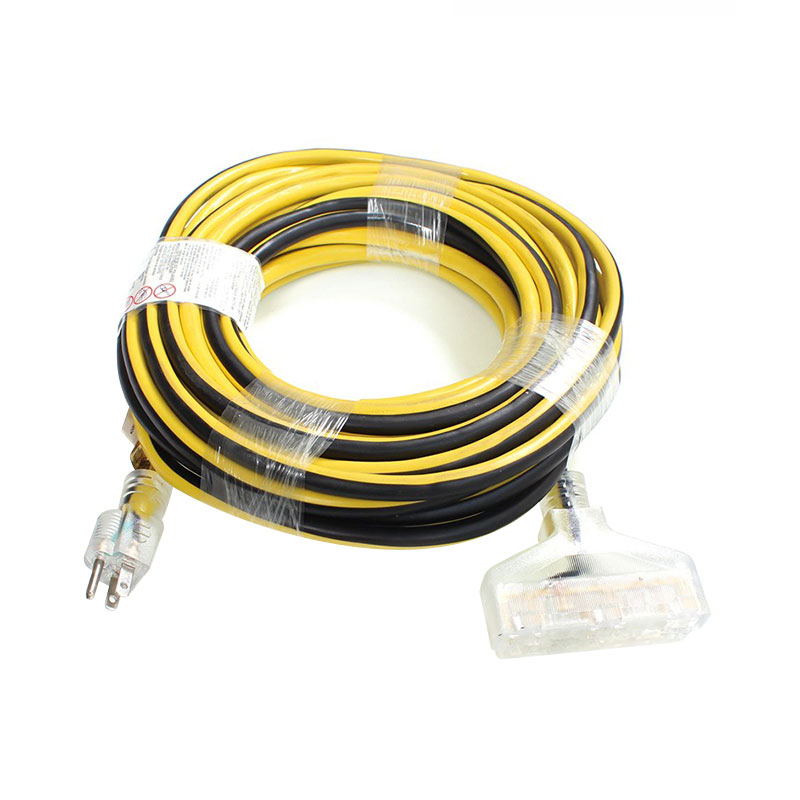
Outdoor extension cords are typically marked with “W” in the cord type, such as SJTW. The W stands for weather-resistance. A durable orange jacket is common because it is visible across a lawn or construction site. The orange color also reduces the risk of someone tripping over the cord or driving over it accidentally.
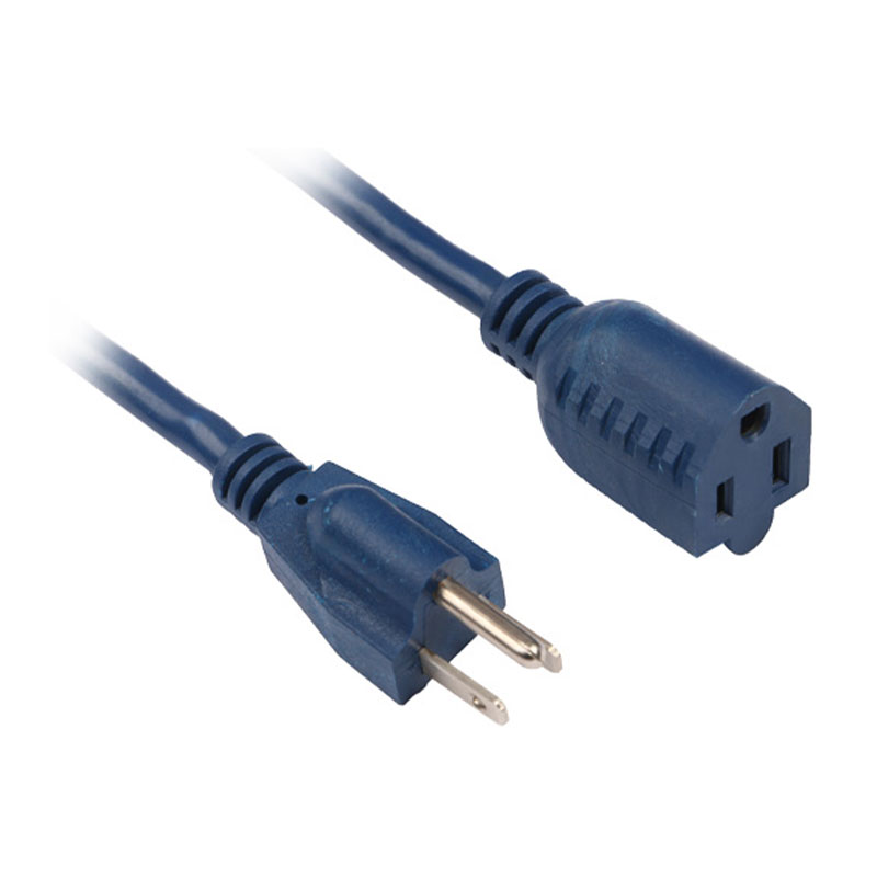
When you buy a ready-made outdoor extension cord, look for a grounding prong and a jacket that resists moisture. A quality outdoor cord is manufactured with a precise wiring diagram, tested for continuity, and built to last through years of exposure. Check that the plug has a solid, molded body with no cracks, and that the strain relief is reinforced.
Outdoor cords may also be fitted with a built-in circuit breaker or an inline GFCI. These devices are wired in series with the hot conductor. The wiring diagram for such a cord will show the GFCI module connected between the male plug and the female receptacle. If you are repairing one, be aware that the GFCI module is a sealed component and should not be opened.
When Should You Replace Instead of Repair?
Sometimes the safest choice is to buy a new cord instead of repairing an old one. If the outer jacket is cracked, brittle, or shows signs of melting, the wiring may be damaged throughout. A wiring diagram cannot fix a damaged core.
If the cord has been kinked, pinched, or exposed to chemicals, the internal wires may have broken strands. You can test the continuity of each wire, but if a wire is broken inside the jacket, the repair is expensive and not worth the effort.
Here are the signs that you should replace the cord:
- The outer sheath is cracked or peeling.
- You see melted insulation or scorch marks near the plug.
- The cord is warm to the touch after running a light load.
- One of the prongs is loose or bent.
- The cord is old and the jacket has become hard and brittle.
- You hear a cracking sound when you bend the cord, which indicates the rubber compound has aged.
When you replace a cord, you need to choose one with the correct gauge and plug type. That is where a manufacturer's specifications become valuable. A cord that is rated for the same current and voltage as the original will perform correctly and safely.
Matching Extension Cords to Equipment and Applications
Every electrical appliance has a specific current draw. The wiring diagram inside the equipment manual or on the nameplate tells you the required voltage and amperage. To select the right extension cord, match the cord's ampacity to the load and account for the distance.
| Appliance | Amps | Recommended Gauge (up to 25 ft) | Recommended Gauge (100 ft) |
|---|---|---|---|
| Lamp / electronics | 2-5 A | 16 AWG | 14 AWG |
| Drill / saw | 10-15 A | 14 AWG | 12 AWG |
| Air conditioner / heater | 15-20 A | 12 AWG | 10 AWG |
| RV / generator | 20-30 A | 10 AWG | 10 AWG |
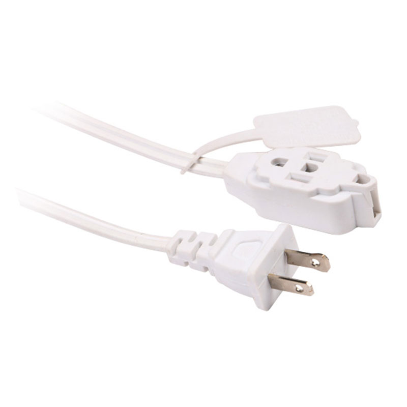
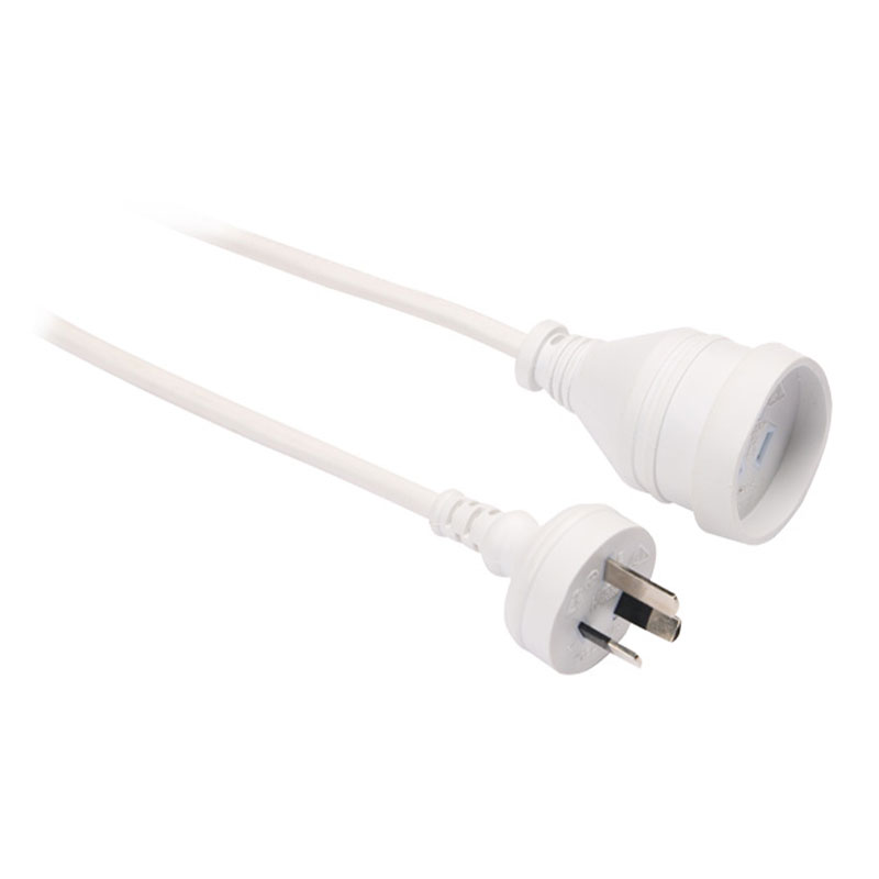
When you are wiring a custom cord for a specific application, obtain a wiring diagram that matches the plug and receptacle. For example, a European extension cord with a Schuko plug will have a different diagram than an American cord. The live and earth pins are positioned differently. In Australia, the standard cord uses a three-pin plug with angled pins, and the wiring colors are similar to the European scheme but with the earth pin at the top.
A supplier like a professional manufacturer can provide cords matched to your market standards. In the case of our own site, we manufacture extension cords for North American, European, and Australian standards, each with the correct wiring and compliance.
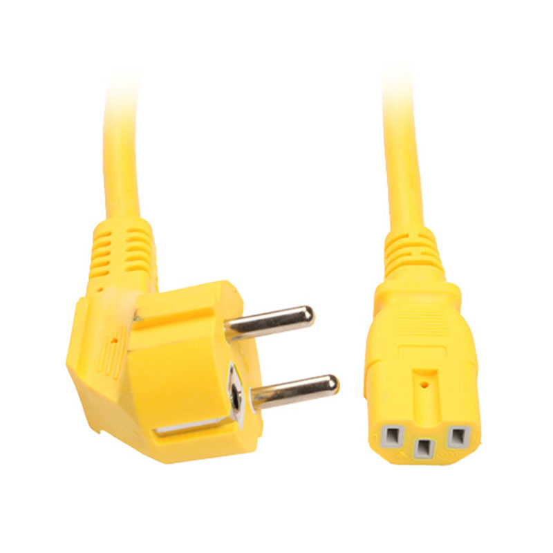
This is the type of detail that most consumers never see: the wiring diagram is the foundation for the plug and receptacle, the wire colors follow the regional code, and the strain relief is designed for the specific cord type. When you order from a manufacturer, ask for the wiring diagram or the specification print.
For industrial machines, the extension cord must often handle a continuous load without heating. A 12 AWG cord with a 20A plug is common for motors and pumps. The wire strands inside must be flexible enough to withstand movement, and the jacket must resist oil and abrasion. If the equipment uses a twist-lock plug, the wiring diagram must be followed closely because the blades are not interchangeable.
Selecting a Quality Extension Cord from a Manufacturer
If you are sourcing extension cords for resale, for an appliance OEM, or for industrial use, you need more than a wiring diagram. You need a manufacturer that can produce a consistently safe product.
Check the following when qualifying an extension cord supplier:
- Does the manufacturer have a documented wiring diagram for each plug type?
- Are the wire colors consistent with the destination standard?
- Are the connectors certified by a recognized body, such as UL, CE, or SAA?
- Does the factory test each cord for continuity, polarity, and insulation resistance?
- Can the manufacturer customize the cord length, gauge, and plug type to your product?
- Does the supplier have a stable production process that prevents variations in terminal torque and strain relief tension?
A manufacturer that has been making extension cords for decades will have a large catalog of product variations. At Danyang Feipeng Electrical Appliance Co., Ltd., we have been designing and manufacturing extension cords and power cords since 1990. Our production line covers everything from household multi-outlet cords to heavy-duty outdoor cords, and each one follows a clear wiring diagram and quality control process.
When you are evaluating a cord visually, you can look at the plug. A quality molded plug will have a firm, solid body with no cracks. The wires inside should be neatly clamped, and the strain relief should grip the jacket securely. If you open the plug, the terminals will have the correct colors matching the wiring diagram.
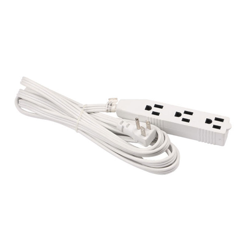
For household applications, a multi-outlet extension cord is often more convenient than a single-socket cord. A quality household extension cord with two or three outlets is made with the same wiring diagram as a single-socket cord, but the female end has multiple receptacles connected in parallel.
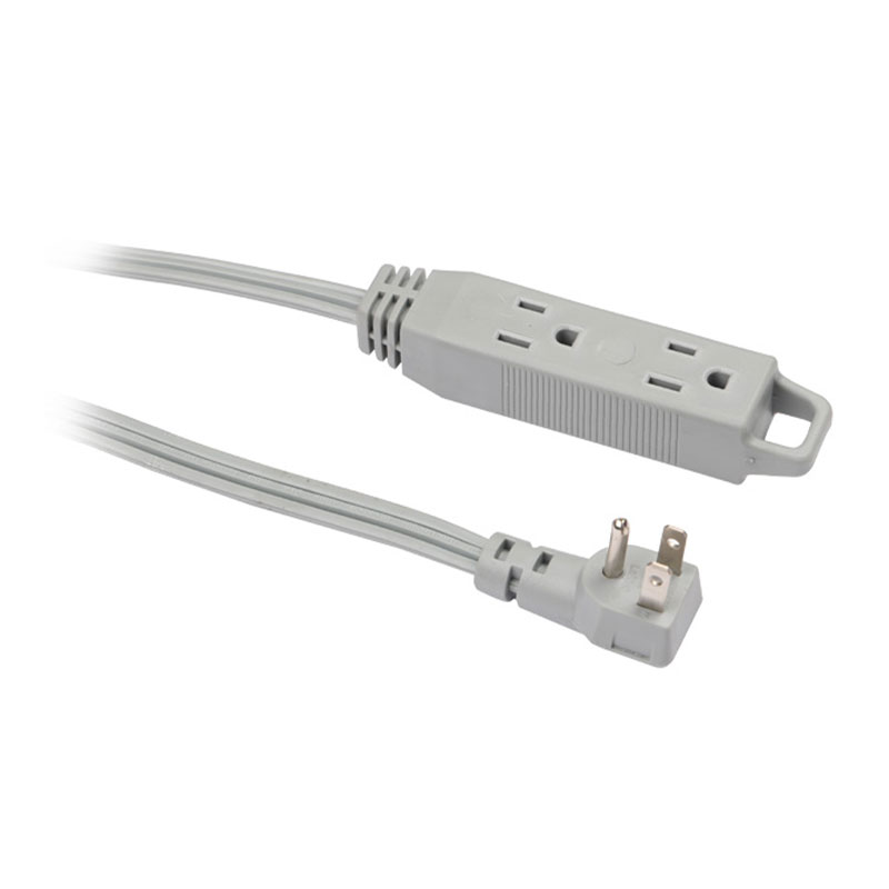
When you manufacture a multi-outlet cord, the wiring is simple: the hot wire loops from one terminal to the next, the neutral does the same, and the ground does the same. The diagram for such a cord will show the daisy-chain connections clearly. Each outlet must be wired in the same polarity, so a receptacle tester at any socket will show a correct reading.
You should always request a product specification sheet that shows the wire gauge, the cord type, and the wiring diagram. This document is essential for your own quality checks and your customer's safety. A manufacturer who cannot provide a wiring diagram or a detailed spec sheet may not be maintaining consistent production quality.
To understand how extension cords are applied across different equipment categories, you can explore our application guide on extension cords designed for various electrical appliances. That page explains the practical differences between cords used for heating devices, lighting, and power tools.
For international buyers, the manufacturer must show that they can build cords for multiple markets. This includes US standard, European standard, and Australian standard versions. The wiring diagram for each market is not the same, so a flexible supplier is critical. A factory with in-house laboratory testing can verify the dimensional accuracy and electrical properties of the finished cord before it is packed.
Extension cord wiring diagrams are the blueprint for safe and reliable electrical connections. Whether you are replacing a damaged plug, building a custom cord, or sourcing cords for production, the same principles apply: identify the hot, neutral, and ground conductors; follow the regional color code; select the correct wire gauge for the load and length; and test the finished cord before use.
We have covered the standard color codes for North America and Europe, the internal construction of common cord types, step-by-step wiring procedures for both male and female ends, and safety precautions. We also discussed how to choose the right gauge, how to test a cord, and how to match a cord to a specific application. The wiring diagram is not a piece of paper you hide in a file; it is an essential tool for actual work on the cord.
By taking the time to read a wiring diagram and to understand what each wire does, you can avoid costly mistakes and protect yourself from electrical hazards. If you need a reliable source for extension cords, look for a manufacturer with decades of experience, a comprehensive product range, and documented quality control.
If you are an industrial buyer, you may also want to review our guide on how to select the right power cord for your industrial application, which covers load calculation, jacket selection, and regulatory considerations for power cords in a factory setting.
Latest Updates
Provide You With The Latest Enterprise
Provide You With The Latest Enterprise
and Industry News.
We will continue to focus on the intelligent temperature control field and serve global users with technical concepts of "safer, more energy-efficient and more environmentally friendly".
-
Industry News
The Ultimate Guide to Immersion Water Heaters: From Portable Heating to Safety Best Practices
11
Feb 2026
Be the First to Know
For exclusive deals and latest offers, sign up by entering your email address below.
-

Provide one-stop service from design optimization, process improvement to volume delivery.
-
Quick Links
Home Products About Us Advantages Application News Contact Us -
Products Categories
Immersion Water Heater Extension Cord Power Strip Power Cord Heating Element Hot Plate Magnesium Anode Rod Electrical Water Heater Stem Thermostat -
Contact Information
Add : Feida Industrial Park , Houxiang Town, Danyang City , Jiangsu Province ,China
E-mail: gm@cnfpdq.com
Tel: +86-13306103666
Fax: +86-511-86321126
Copyright © 2025 by Danyang Feipeng Electrical Appliance Co., Ltd. All Rights Reserved.
 Custom Electric Heater Components Manufacturers
Custom Electric Heater Components Manufacturers